|
Early Vidicon TV Camera |
 |
| Seen here is a
television camera which may have originated within
the Philco Corporation, probably in the mid 1950's. The camera was purchased from the estate of an
engineer who worked for the Philco-owned
television station, WPTZ, in Philadelphia. He also, it would seem,
had a side business producing videos of a rather unsavory nature, and it
is possible that this camera played a part in that operation. It has no markings that could absolutely confirm its origin, but there are some interesting clues in its components and construction. The camera measures about 17 inches long, 10 inches high, and 7 inches wide. It weighs about 25 pounds. Unfortunately, the original side panels are missing. It uses a Vidicon image pickup tube. The Vidicon was originally developed in the late 1940's as a smaller and cheaper alternative to the Iconoscope and Image Orthicon tubes that were available at the time. The first Vidicons were only about 6 1/4 inches long and about 1 inch in diameter (the Image Orthicons were about 15 inches long and 3 inches in diameter). Vidicons were used in a wide variety of applications. Most commonly, they were used in industrial and surveillance cameras. Certain tubes were of high enough resolution for commercial broadcast applications. Vidicons made portable cameras possible, which made live TV journalism possible. The Vidicon that was installed in this camera was an RCA developmental type from 1950. |
 |
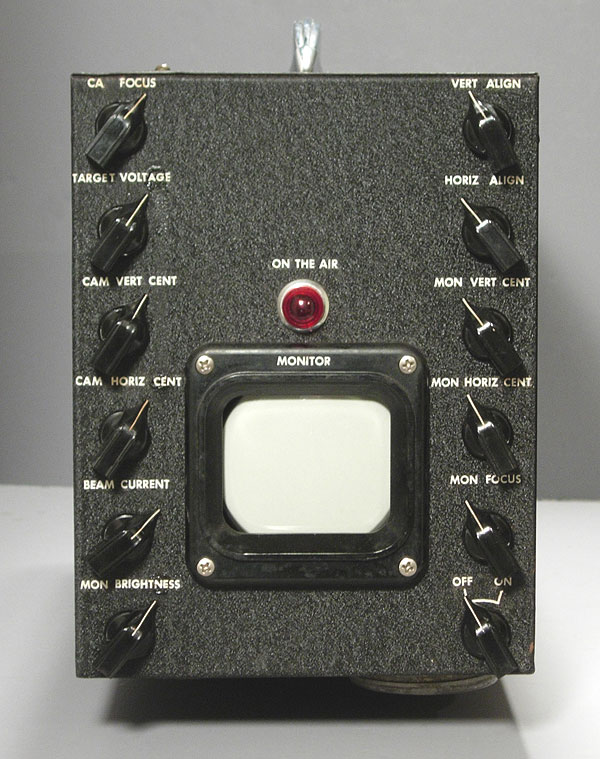
| It seems clear that this
camera was intended for broadcast rather than industrial use. A 3-inch diameter monitor using an RCA 3RP4 tube was provided for the operator. The red "tally light" just above the monitor is marked "On The Air", and the two lights on the opposite end were there to warn the subject that the camera was "live", and to not do or say anything stupid or embarrassing. |
 |
| This camera was equipped with a single lens which appears to have been scrounged from a 16 mm movie camera (it is Japanese). It may not be original. |
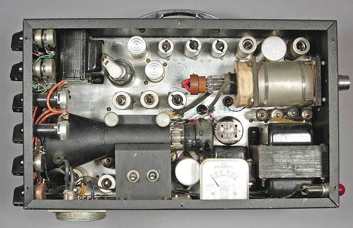 |
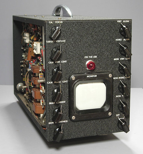
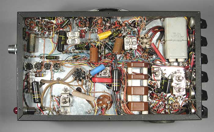
| This view shows the
interior of the camera. At the top right is the Vidicon tube
mounted in its cylindrical deflection yoke housing. At the lower
left is the monitor CRT in a shield which isolates it from external
magnetic fields (which would distort the image). The transformer
and filter choke in the lower right provides the power for most of the
camera's circuitry, and the transformer in the upper left corner
provides the high voltages required for the operation of the monitor
CRT. The meter, I believe, is there to measure the Vidicon beam
current. What is NOT present in the camera is of significance. There is no internal sync generator. Cameras intended for broadcast use generally did not have internal sync (synchronization) generators (the circuitry that determined the frequency and timing of the vertical and horizontal scanning which produced the TV picture). Broadcast operations use a central sync generator whose output is distributed to all the cameras. This makes it possible to switch between cameras without visible disruptions in the program. Cameras designed for industrial applications, in general, had internal sync generators. |
 |
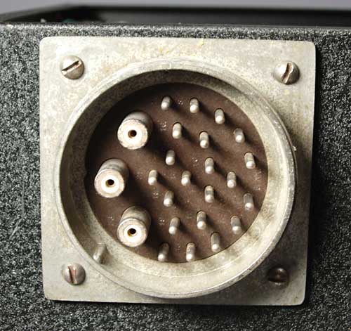 |
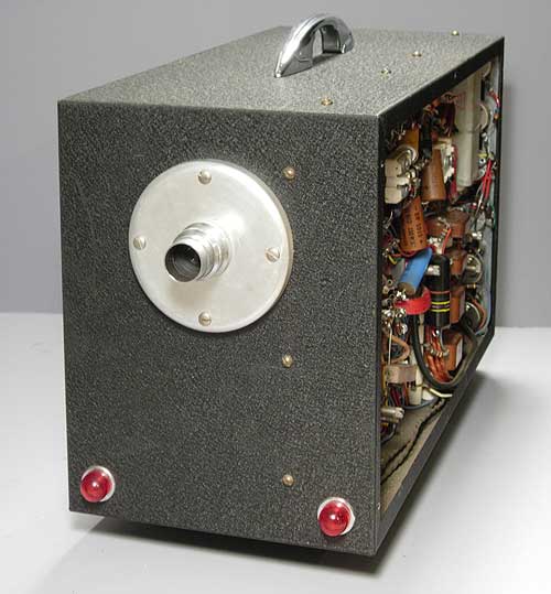
| This multi-pin connector (2.5 inches in diameter) is located on the bottom of the camera. The three large objects on the left are coaxial connectors for the video output of the camera and feed from an external sync generator. Connectors of this type were standard on the broadcast cameras of the period. The presence of this connector on this camera is further evidence that this was a broadcast camera. |
 |
|
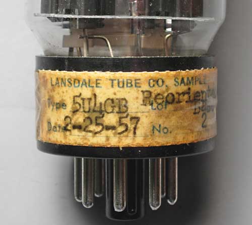
This is a sticker that is
taped to the base of the 5U4GB low-voltage rectifier tube in the camera.
The Lansdale Tube Company (in Lansdale, PA) became a division of the
Philco Corporation following its purchase in 1947 from the National
Union Radio Corporation.
The sticker indicates that the tube was specially made with the base rotated 22.5 degrees from its standard orientation. The only reason to do this would have been to improve reliability when the tube is mounted horizontally, as it is in this camera. However, creating a special tube just for this camera makes no sense, as the same effect could have been achieved by simply rotating the socket in the chassis. So, when was this camera built, and by whom? A majority of the other tubes in the camera are of Philco manufacture, and they bear date codes running from 1951 through 1957. There is no way to know if any were replaced, though. The meter inside the unit provides another clue in the form of a patent number which was issued in early 1954. Assuming it is original to the camera, it couldn't have been built before then. Research on the Internet turned up a mention of a transistorized Vidicon camera that was developed by Philco in 1956. If this is a Philco prototype, it would have to be earlier than that. Several other companies marketed broadcast Vidicon cameras in this time period. This camera is very similar to the 1955 Dage 101. Of course, this may have just been a "home project" built by a Philco engineer, using whatever parts he could scrounge from his employer (an unstated fringe benefit of his employment). He was more than capable of successfully undertaking a project of this magnitude. I will probably never know for sure, but I would welcome any comments and additional information. |