|
Holmes Electric Protective Company Burglar Alarm |
 |
|
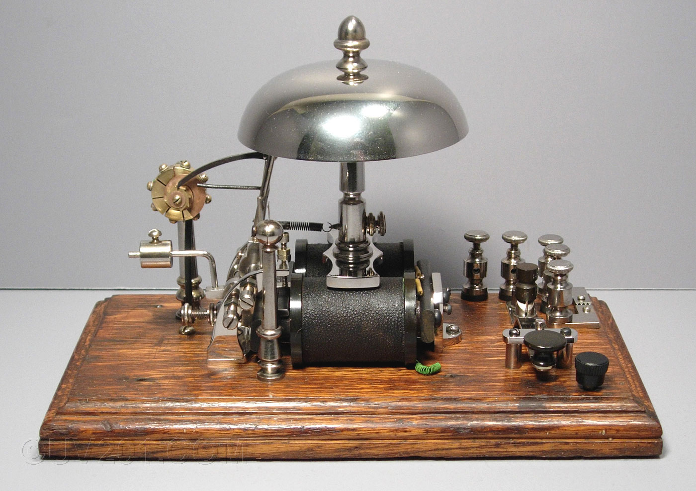
The device shown here is a portion of a burglar alarm system made by the Holmes Electric Protective Company in the 1890s. It was the subject of US patent no. 540,341 issued to James Tomney of New York, NY. The application for this patent was filed on May 2, 1892, and it was issued on June 4, 1895. A brief history of the Holmes company can be found here. This device has been totally restored. Click here for a series of pictures of how it looked when I acquired it. The Holmes company maintained central offices from which alarm systems in multiple remote locations could be monitored. A single wire connected the central office to each client's location, with the earth ground completing the circuit. The wires were strung on telegraph or telephone poles whenever possible. In many cases, the wires were simply strung across rooftops, generally without the owner's knowledge or permission. These were urban installations, most often in commercial areas, with flat rooftops that made this technique feasible. Each installation employed a number of contacts mounted on windows, doors, or other potential entry points, or on safes and vaults. These contacts were normally closed, but would open if, for example, a door were forced open. In operation, an electric current flowed from batteries located in the central office, through the coils of a sensitive relay, then through the outside connecting wire to the protected building, and finally through each of the contacts. If any contact opened, the current flow through this loop circuit would be interrupted to sound the alarm. The relay (which Holmes called a galvanometer) was used to monitor this current flow. It could be adjusted to hold it's contacts open as long as the current flow was within predetermined limits. If the current exceeded the upper limit, or dropped below the lower limit, the contacts would close, and activate an alarm bell. To make the system resistant to tampering, a resistance was inserted into the loop. This resistance, plus the resistance of all of the connecting wire, and the battery voltage, determined the normal current flow. The galvanometer had to be adjusted to this normal condition. A burglar might have assumed that cutting the wire, or grounding it, would have rendered the alarm inoperative. He would have been wrong, as either action would have sounded the alarm. If a more sophisticated burglar knew the resistance that was supposed to be in the circuit, he could have shunted the wire to ground through his own resistor just as he was cutting the wire. To prevent this, the Holmes system made the task much more difficult by allowing the loop resistance to be changed at random intervals so the burglar would not be able to know for certain what the correct resistance would be at any particular time. |
 |
|
The device shown here was installed at a protected location. It provided the means by which the loop resistance could be changed on command from the operator, and it also served as a communication device (a simple telegraph), between the central office and the client's location. During normal business hours, the alarm was disabled. As the last employee secured the location, he would signal the central office by pressing the buttons in the lower front right corner of the device. This alerted the alarm watchman to begin monitoring that particular circuit. The watchman would then respond that the signal was received by ringing the bell. A commutator device was linked to the bell through a pawl and ratchet mechanism. The commutator consisted of eight fixed contacts shaped like pie slices, and a rotating wiper which made contact with one of the eight segments. Each time the bell was rung, a pawl rotated the ratchet wheel 1/8 of a turn, and selected the next fixed contact. These contacts were connected to wirewound resistors mounted under the base board. This particular unit was designed to offer only two loop resistances. Other models, apparently, had more. The bell requires considerably more current than would have normally been flowing through the alarm loop circuit. To make it ring, the operator switched in a higher voltage battery. This higher voltage was still insufficient to operate the bell because of the loop resistance, but it was enough to close a set of auxiliary relay contacts actuated by the same coils that rang the bell. These contacts then shorted out the loop resistance, allowing the maximum possible current to flow through the coils. This additional current was enough to ring the bell and step the commutator. |
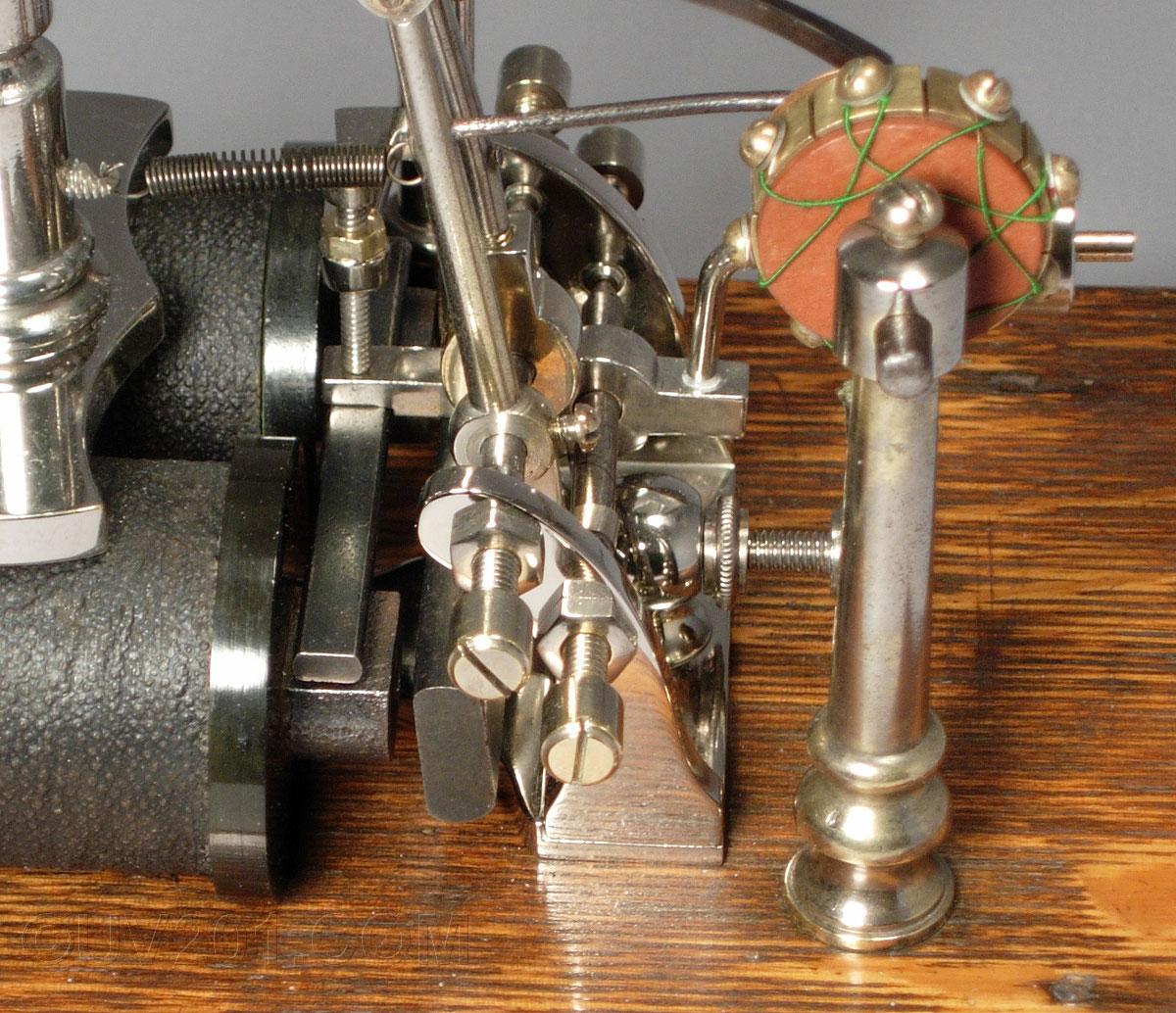 |
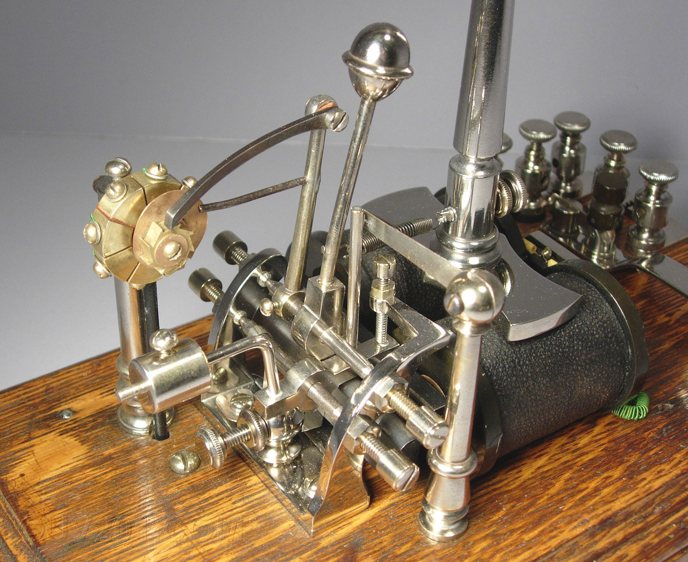
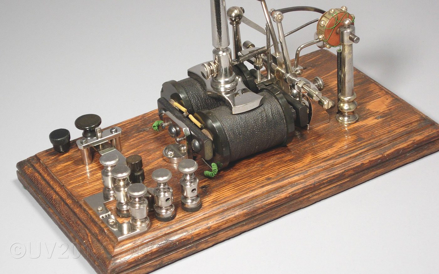
| In this view, you can see the wiring on the commutator. Not also the two armatures acted on by the two coils. The larger operates in the horizontal direction, and operates the bell and the commutator. The smaller, more sensitive one operates in the vertical direction, and operates the auxiliary relay contacts. |
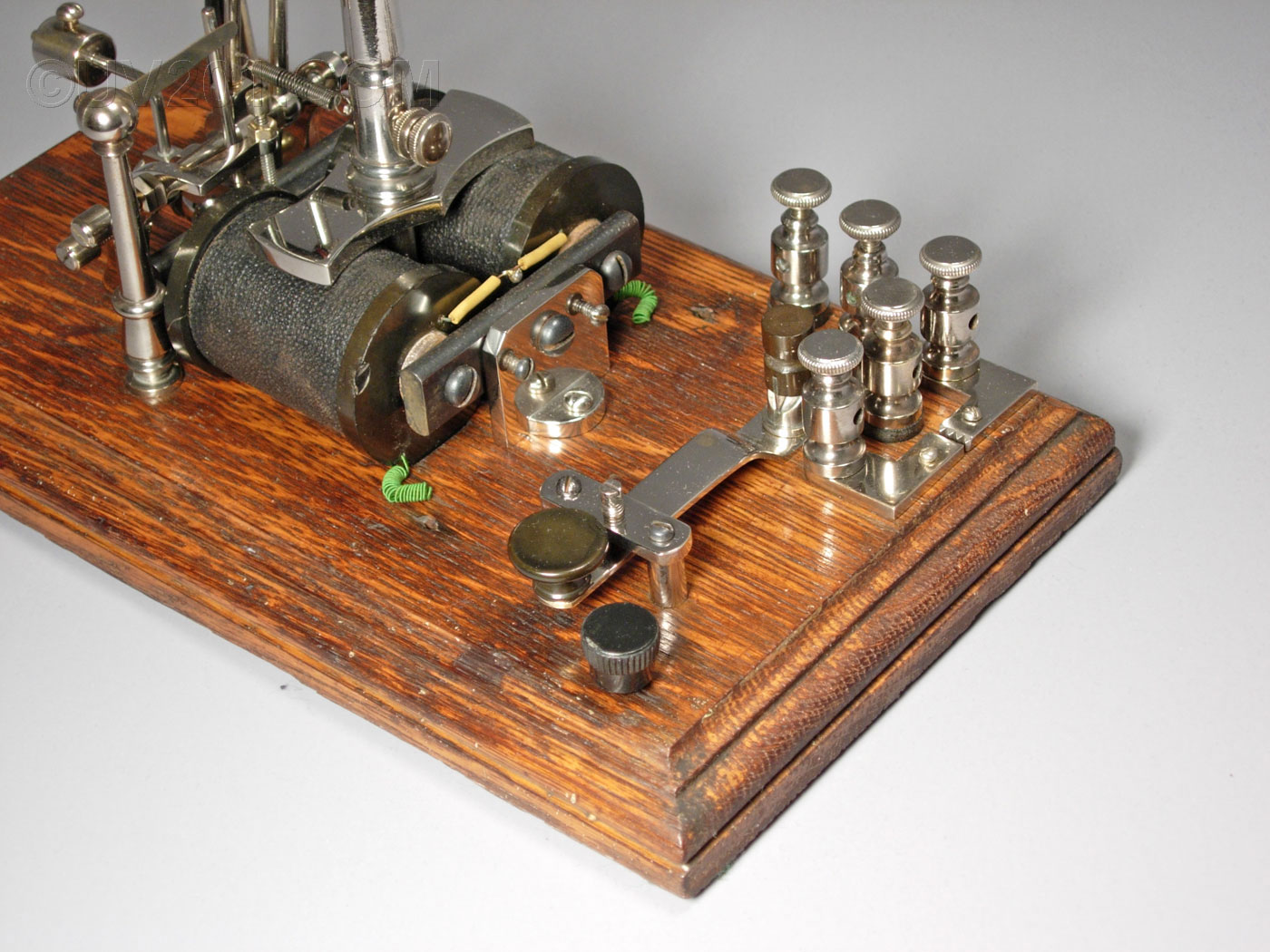 |
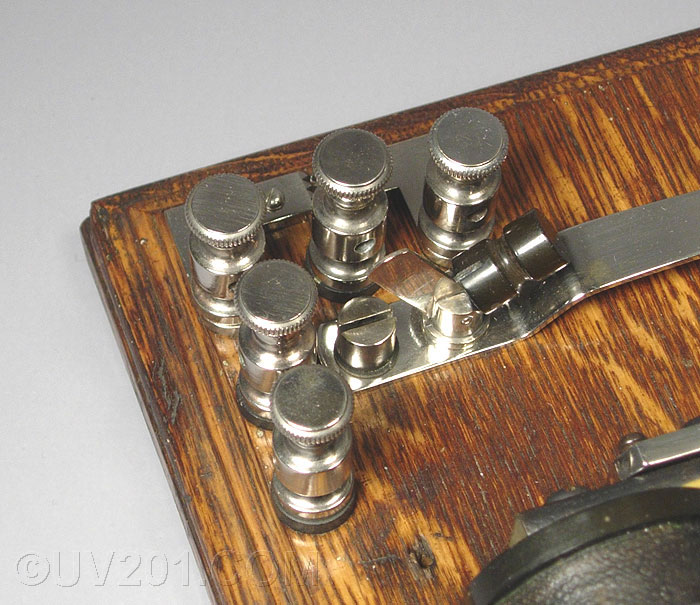
| This view shows the two
buttons used to send a signal to the central office. The cap on
the button nearest the corner is not original, and was missing when I
acquired the unit. I believe it should match the one on the
keyswitch. A small knife switch is visible at the back end of the keyswitch. When open, it breaks the loop circuit and disables the alarm. A sawtooth type lightning arrestor can be seen in the right rear corner. |
 |
 |