|
Western Electric CW-926A Restoration |
|
 |
|
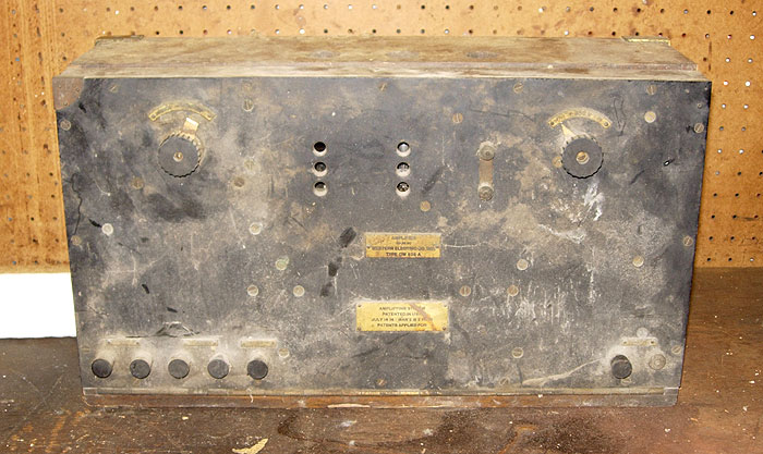
| This page is
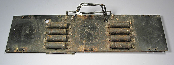
devoted to the restoration of this Western Electric CW-926A amplifier. The first
picture shows what it looked when I brought it home. The dirt on the outside gives
only a hint of what it was like inside. (Please note: several pictures on this page have clickable links to higher resolution versions.) |
|
 |
|
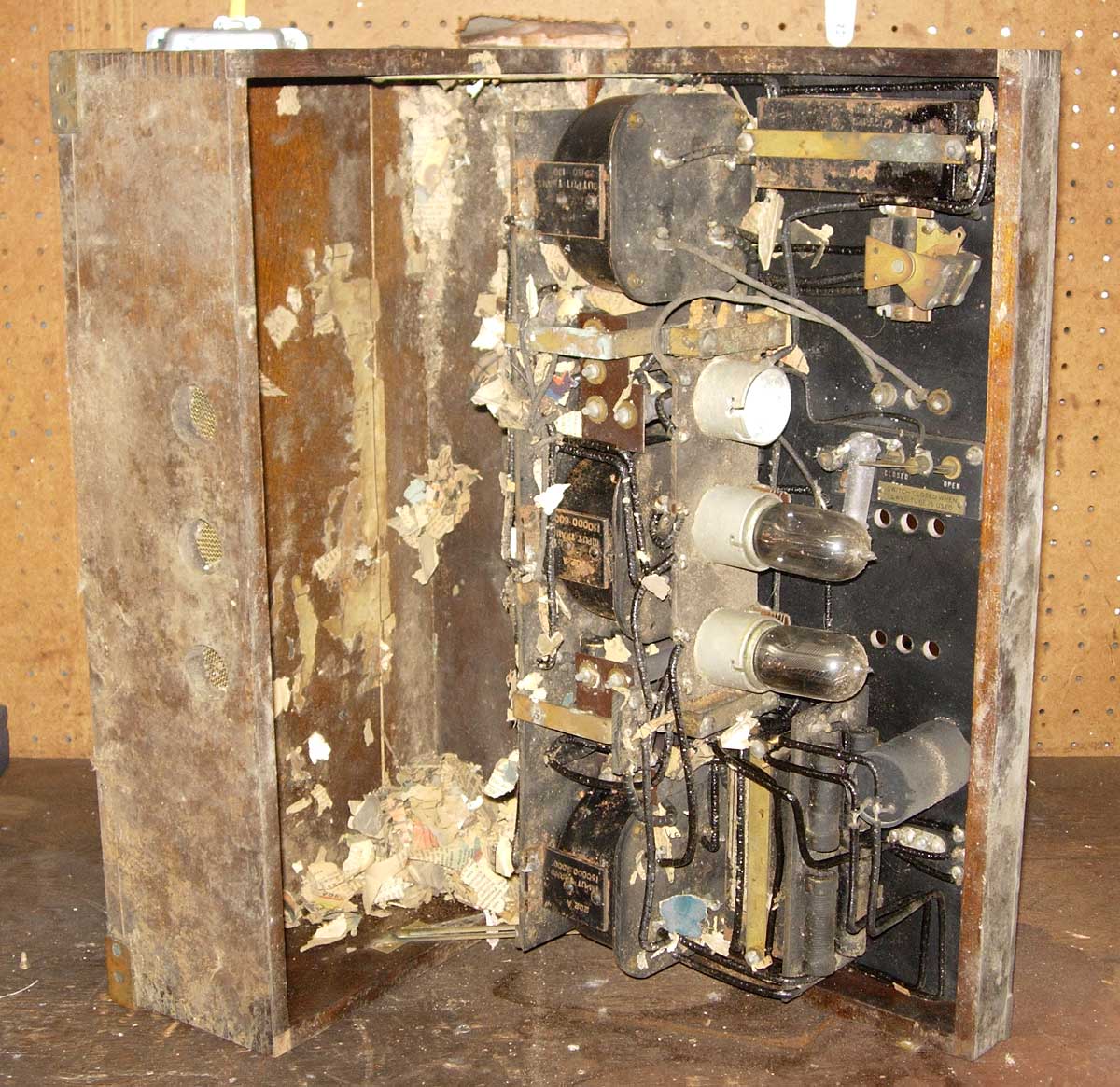
| This unit spent
decades stored in a shed in central Pennsylvania, along with it's
companion speaker. It was home to
many generations of mice who brought shredded newspaper into the cabinet
to make their nests. Only a fraction of that newspaper is still present in this
image-the lower sections were solidly packed! The dirt inside is so pervasive and so inaccessible that it quickly became clear that only a complete disassembly would make cleaning possible. This was obviously not going to be an evening project. The wood cabinet had suffered considerably. The bottom panel had warped and split, and the rodents had further damaged the wood by gnawing at it. Several pieces of the brass cabinet hardware were missing and the original shellac finish was in bad condition. The schematic diagram that was glued to the inside back of the cabinet was almost completely destroyed. This unit was probably sold as surplus by the Navy in the early 1920's. Once in civilian hands, two binding posts were added to allow the insertion of headphones into the plate circuit of the output tube as an alternative to the low impedance CW-929 horn. Fortunately, the new owner used the existing tube inspection holes for this, rather than drilling new holes. One resistor was replaced, which is visible just behind the tubes in the previous picture. One of the seven binding posts had been broken off and lost. |
|
 |
|
| Some years before finding
this unit, I was fortunate to have found an empty CW-926A cabinet. Someone had
laboriously stripped the front panel, and there was nothing inside but
dirt. This second cabinet
was actually in much better condition, having only some worm damage and
minor splitting, so it is this one that will
be restored. Between the two units, I was able to put together one
complete set of cabinet hardware with the exception of the missing brass corner
protector at the top right, which was an easy task to fabricate. The schematic diagram in this cabinet was about 95% intact and mostly readable, which was a big help in the restoration process. Most of the wiring is no. 14 solid copper wire (identical to house wire of the same size). All connections to the shock-mounted tube socket assembly were made with flexible stranded wire. All of the wire was insulated by sleeving that had a cloth base with a rubber coating. Almost without exception, the old sleeving was badly deteriorated, and would crack or crumble under any stress. At least the mice did not find this material to be edible. I located a modern product consisting of woven fiberglass with a PVC coating that looks astonishingly like the original, so I decided to replace the old sleeving with this material. The key components in this amplifier are the three transformers. A continuity test revealed them to be functional. At this point, I decided that it made sense (?) to restore the unit to full operating condition since it would be apart anyway. |
|
  |
|
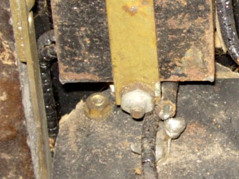
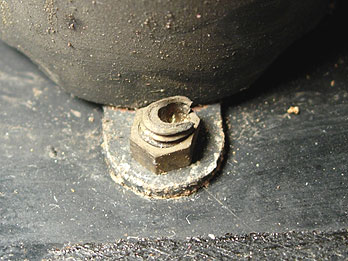
| Typical of Western Electric WW-I military electronics, virtually every piece of hardware in this unit was either soldered (left) or punched to prevent loosening when subjected to vibration. There is not one lock washer anywhere in this unit. Though tedious, removing the soldered hardware is not very difficult. Removing the punched hardware intact is nearly impossible, however, and they must be cut or ground out. | |
 |
|
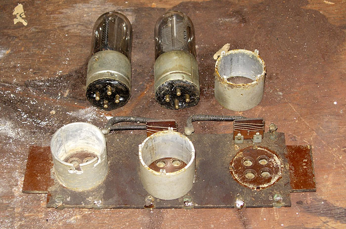
| The first step was removing the tube socket assembly. It consisted of a phenolic panel and three aluminum socket shells. Two wirewound resistors can be seen at the rear. The two VT-1 tubes that were present were stuck firmly in their sockets. | |
 |
|
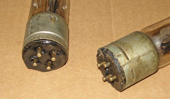
| The tube bases
are filled with a black wax
insulating compound that had melted, run down, and rehardened, reducing the clearance between the bottom of the tube and the phenolic
base
panel to zero. This made it impossible to remove the tubes since
it is necessary to push the tube down in the socket and then rotate it
to allow the bayonet pin to release the tube. The socket on the left was apparently hacked up to allow a failed tube to be removed. The remaining tubes could only be removed once the socket shells were removed from the phenolic base, and that was only possible once the entire assembly was removed from the amplifier. A report that was issued within the Western Electric company after the end of WW-I mentioned this melting wax problem as it was experienced in service on the sub chasers. The original wax that they used had a melting point around 160° F. They found that the temperatures experienced in operation went as high as 225° F! That is almost incomprehensible, and it speaks volumes for the fortitude of the sailors who served on those ships. A higher temperature wax filling compound was developed which was an improvement, but a recommended change to a phenolic insert as used in the VT-2 tubes was never implemented as the war ground to its conclusion. The two tubes that were still in the unit were apparently there since the amplifier was installed on a sub chaser. Once removed, they tested well, so I remelted the wax and pressed it back into the shells. The original tubes are now back in the sockets which held them for the last 90 years. The socket shell on the left (for the output tube) has two bayonet slots in it, allowing either the VT-1 or VT-2 type tubes to be used in that position. The VT-2 tubes had bayonet pins offset by 45 degrees from the standard position. This prevented inserting one of these tubes into the wrong socket. When I acquired this amplifier, a VT-2 was installed in this socket, which was still usable for that tube type. A replacement was fabricated, however. |
|
 |
|
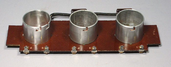
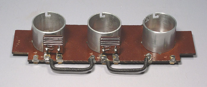
| The restored
tube socket assembly is seen here. Both of the resistors were
rewound using modern Nichrome resistance wire.
The original wire was made of an iron-containing alloy which had rusted
and become brittle. Interestingly, the Nichrome wire of the same
diameter as the original has the same resistance characteristics, so
they perfectly match the originally specified value. A standard size of aluminum tubing was almost the right size for the replacement shell, but it had to be ground out on the inside to provide sufficient clearance. Note the two original shells have vertical slots which allow them to expand a bit, though this slot was probably only a result of their having been fabricated from sheet stock that was rolled into the necessary round shape. After several hours of hand work, the new shell looked so nice that I didn't want to risk ruining it by cutting the slot, so I left it that way. |
|
 |
|
 |
|
| The tube sockets are shock mounted between pieces of tan-colored foam rubber. After 90 years, it has the consistency of dry toast. Any disturbance turned it to dust. Foam rubber in any other color than black is hard to find, so that's what I had to use to replace it. Hopefully, I will be able to find something closer to the original. | |
 |
|
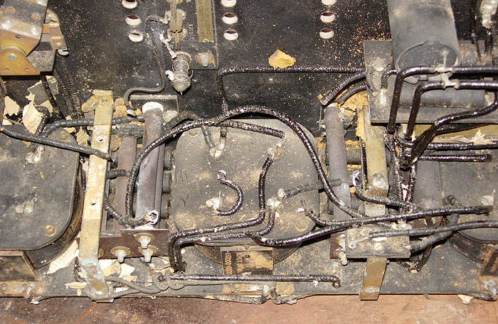
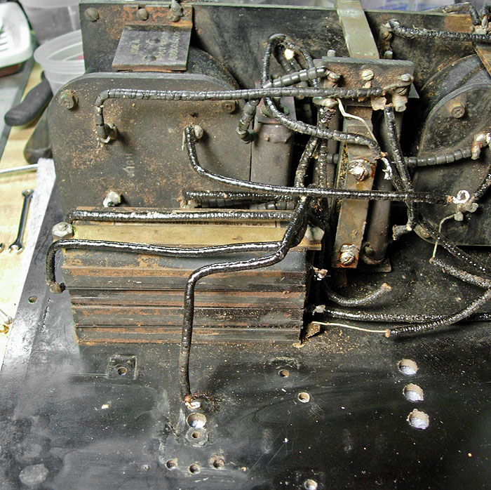
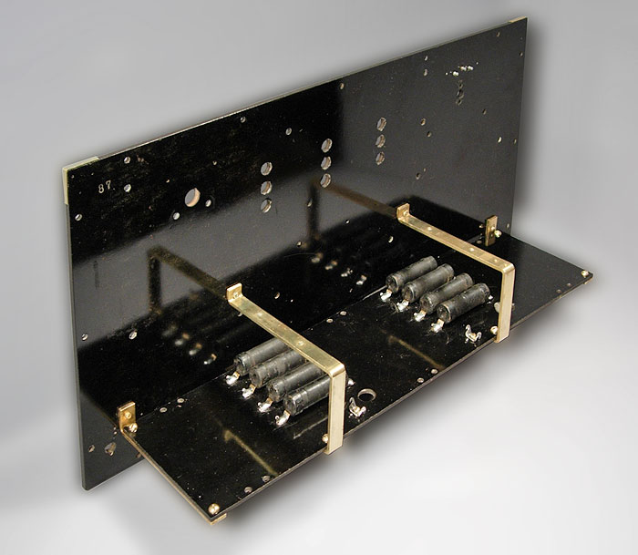
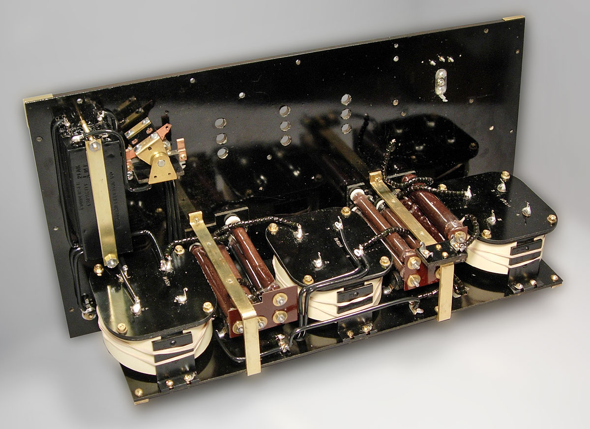
| Once the tube
socket assembly has been removed, the center transformer is revealed.
On either side of the transformer are groups of resistors. The large resistors running front-to-back are plate resistors for the three stages, or voltage dropping resistors in the series-connected filament circuit. Each of these resistors has an asbestos washer at each end which will be removed. Underneath are two additional groups of resistors running left-to-right which are in the grid circuits of the first and third stages. |
|
 |
|
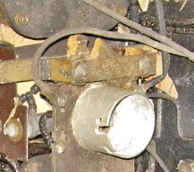
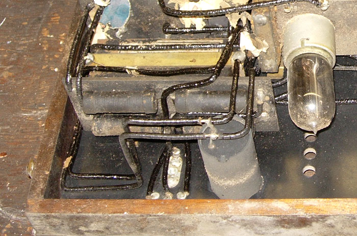
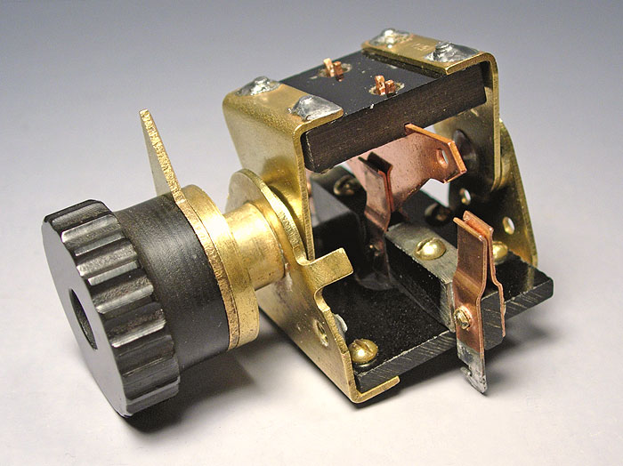
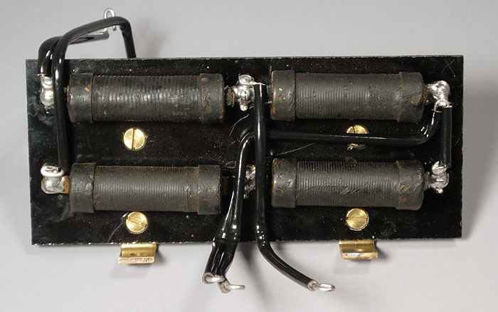
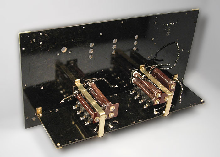
| The volume control for this amplifier consists of a three position switch and a Bakelite panel holding four resistors. The cylindrical object in the foreground is an audio frequency choke (Western Electric called them "retarding" or "retard" coils). | |
 |
|
| Once the volume control components and the choke were removed, the group of four capacitors is revealed. | |
 |
|
 |
|
| Once the transformers are removed, the resistor assemblies are exposed and ready for removal. | |
 |
|
 |
|
| Finally, the subpanel containing the grid resistors has been removed and is ready for cleaning. | |
 |
|
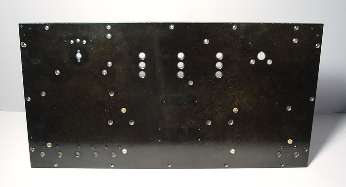
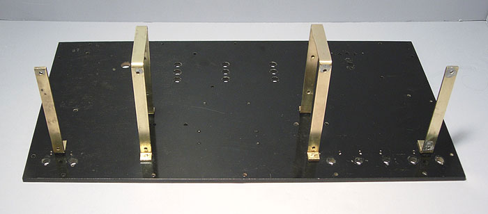
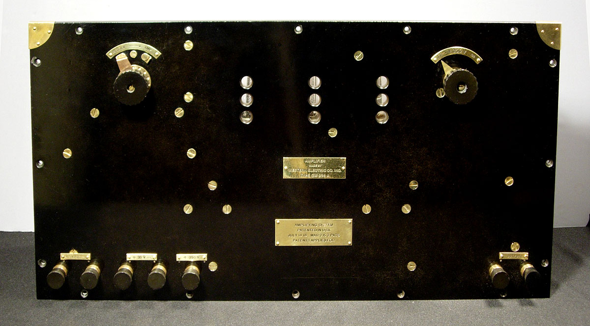
| With most of the hardware removed, the front panel looked like this. The panel is 1/4 inch thick, and is very robust. It is actually in very good condition considering what it has been through. It has only a few minor chips and scratches, and no cracks. | |
 |
|
 |
|
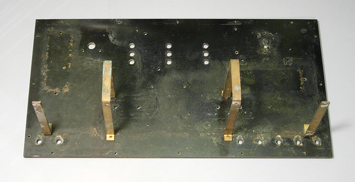
| After cleaning and polishing, the almost bare panel looks like this. The four brass support brackets were not removed to avoid destroying the screws which secured them. Unfortunately, most old Bakelite can never be brought back to its original black color and luster, as they used a considerable amount of a lighter colored filler in the mix which is exposed on the surface with wear and polishing. | |
 |
|
 |
|
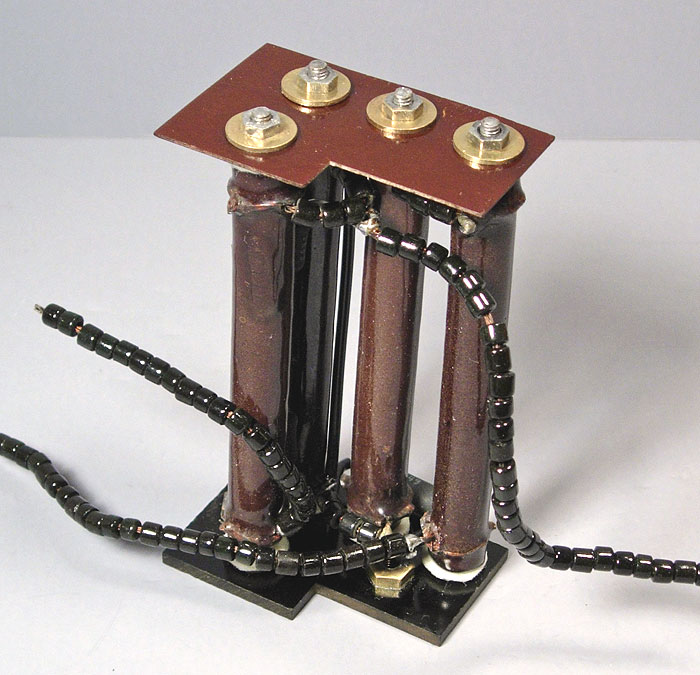
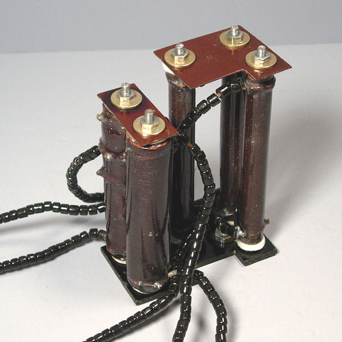
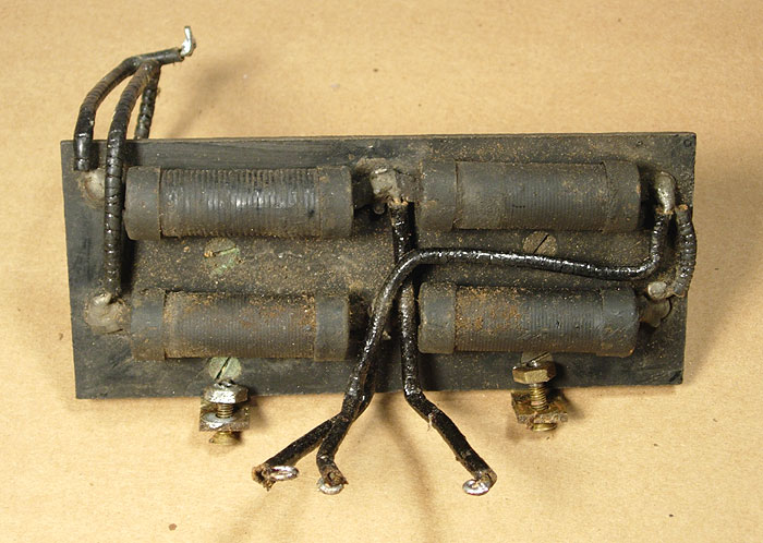
| The two large
resistor assemblies are shown here prior to re-installation into the
amplifier.
The one above consists of a 2K ohm plate supply resistor for the output stage, and a 48K plate supply resistor for the second stage. The one below consists of a 48K ohm plate supply resistor for the first stage and two resistors that are used to generate grid bias voltages for the three stages (8 and 15 ohms) as part of the series-connected filament circuit. The two 48K resistors actually consist of three 12K units in series due to limitations in the technology of the time. At each end is a piece of 1/8 inch thick Bakelite (at the panel end) and a piece of a much thinner phenolic material at the free end. Screws run through the hollow cores of each resistor and hold the assembly together. These resistors did not have solder terminals. Instead, connections were made through uninsulated stranded wire leads. These were insulated with ceramic beads which were appropriate for high temperature operation. I have seen the same beads used in early electric heaters. Fortunately, the two bias resistors are still usable, but most of the plate resistors are open. They are almost identical in size to modern 50-watt resistors, but because of their unique appearance, I sought a different option. Actual measurements on a breadboarded version of the circuit indicated that a 10-watt unit would suffice for the third stage plate resistor, and 2 watt units would suffice for the others. I bridged them with modern resistors with black ceramic coatings that would be difficult to see once installed. Since most of these resistors will never get hot again, I replaced the asbestos washers with ones that I made from white felt. They are totally safe and look very much like the originals. For the two bias resistors, I used fiberglass washers that were also light in color. |
|
 |
|
 |
|
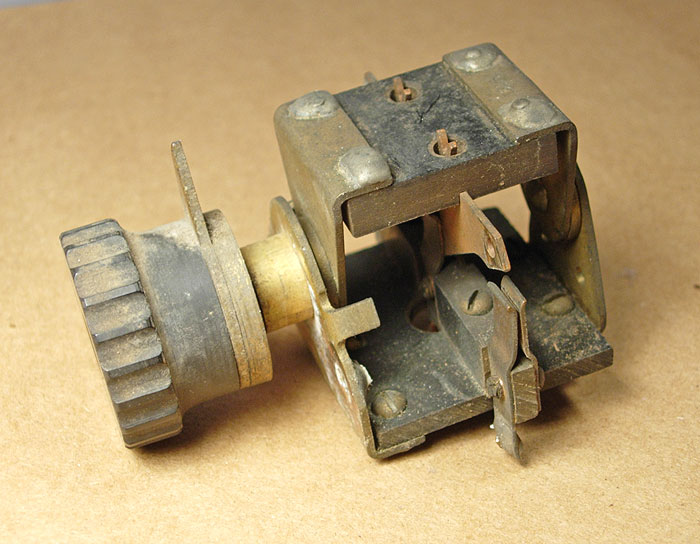
| This is the main power switch for the amplifier. It switches only the 350 volt plate supply voltage (the filament supply is not switched). While the total current flow through this switch would normally never exceed 100 milliamps, it looks like it would carry 20 amps comfortably. | |
 |
|
  |
|
 |
|
| The volume control for this amplifier consisted of a three position switch and four large resistors mounted on a separate 3 by 6 inch Bakelite board. The resistors (one 12K ohms and three 48K ohms) are about the same size as modern 25-watt resistors, though they would have to carry very little current. None are open, but two are far from their original value. I bridged those with modern 1/2 watt resistors to bring them down to the correct values. Since they are hollow tubes, the new resistors hide nicely inside. | |
 |
|
 |
|
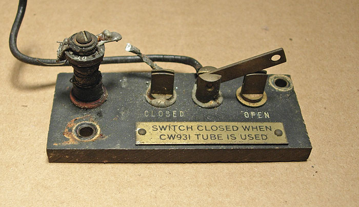
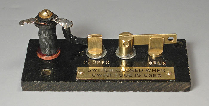
| When using the CW-931 (VT-2) tube in the output stage, an additional resistor is connected across that tube's filament. This switch performs that function. Long ago, this resistor had opened and had been bridged by a newer resistor that can be seen in the full interior view of this unit in front of the middle tube. The open resistor was repaired by rewinding it with modern enameled resistance wire and wrapping it with high temperature fiberglass tape. | |
 |
|
 |
|
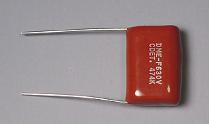 |
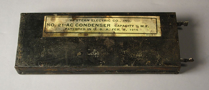
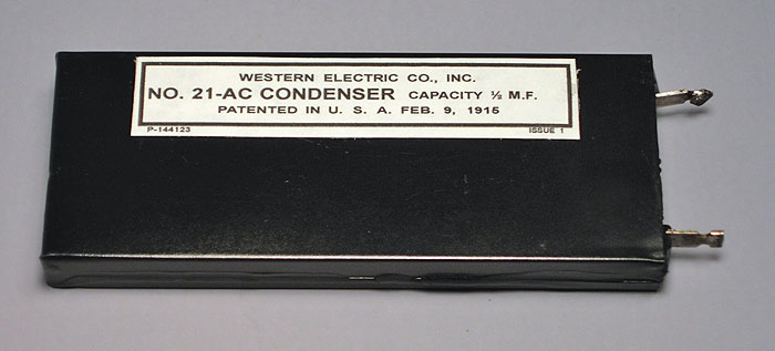
There are six capacitors in
this amplifier. Two are for signal coupling at the input, one is
across the 350 volt supply, and the remaining three are bypass
capacitors for the plate supply of each stage. They are a conventional wax paper and aluminum foil design and were sealed with tar. They were gutted, cleaned, painted and a modern capacitor (tiny, by comparison) installed inside. They were then resealed with the original tar and reproduction labels applied. |
 |
|
|
|
|
| The transformers were cleaned and repainted, and reproduction decals applied. And no, the decal is not upside down-this is the way they came from the factory. Similar transformers in other Western Electric equipment were mounted on vertical panels, so the decal would be correctly oriented in those applications. The word "Company" was off center on the original, so that's how the reproductions were made. These decals were made on an Alps MD-5000 printer using a metallic gold print cartridge. | |
 |
|
|
With all of the components restored and subassemblies
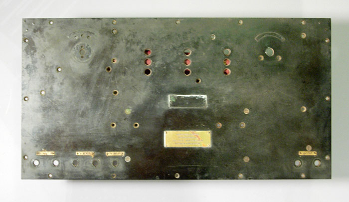
prepared, reassembly of the amplifier can begin. First, the subpanel is installed. Note the number "87" stamped into the rear of the panel in the upper left corner. I believe this is the serial number for the unit. There are no external numerical markings on this unit (other Western Electric equipment of the same vintage have serial numbers stamped into metal plates on the outside of the cabinet). |
|
 |
|
| Next, the resistor subassemblies are added. | |
|
|
|
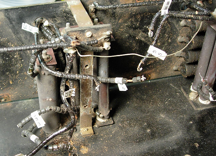
| The three transformers, the volume control switch, and the seven binding posts are installed next. | |
 |
|
| The two capacitors on the left and the power switch have been installed and connected. Most of the wiring to the resistors has been completed. Paper shields held by rubber bands were added to protect the finish on the transformers as this work proceeded. | |
 |
|
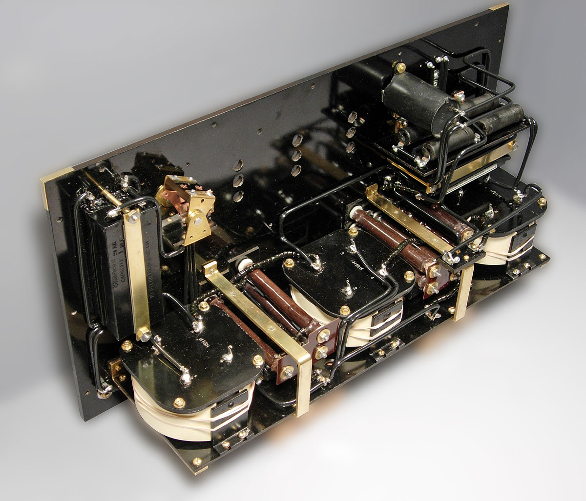
| The volume control components, the choke coil, and the group of four capacitors have been added at the right side. | |
 |
|
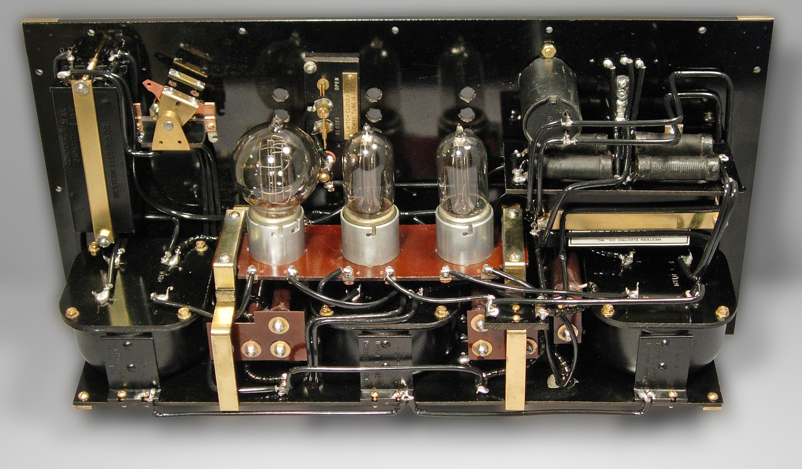
| Finally, the tube socket assembly has now been added, and the wiring is now complete. | |
 |
|
 |
|
|
As has been mentioned, the CW-926A (and some other Western Electric equipment of the same vintage) had the tube filaments connected in series. In this case, the supply voltage was nominally 30 volts DC, as derived from the ship's batteries. The 350 volt plate supply was provided by dynamoters (motor-generators) driven from the same 30 volt supply. Dropping resistors in the filament circuit were used to generate negative grid bias for each of the tubes. The first two stages had bias voltages of approximately -15 volts, and the output stage had a bias of approximately -20 volts. The VT-1 and VT-2 tubes were designed to use filament voltages of 2.3 and 7.0 volts, respectively. In this amplifier, at the rated supply voltage with a VT-2 installed, the VT-1's will operate at very close to their rated voltage, and the VT-2 will have about 6.5 volts on its filament. If three VT-1's are installed, the first two VT-1's will have about 2.8 volts on their filaments, and the final stage will have about 4 volts on its filament. Some VT-2's that I have seen have "4.8" ink stamped on their bases. Presumably, Western Electric had at some point backed off from the 7.0 volt rating in the interest of longevity. The lower voltage was in line with the later versions of this tube, most notably the 205-D, which had a 4.3 volt filament rating. In either case, it is clear that the designers were driving the output tubes very hard, and they probably didn't last very long. |
|
 |
|
|
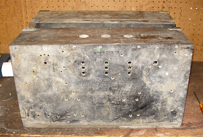
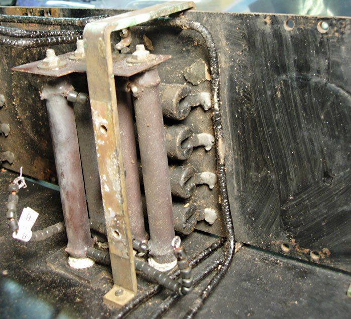
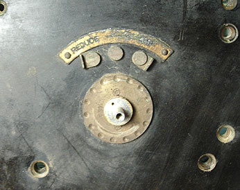
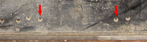
This amplifier also appears to have been an early
unit, probably from the first production run. The number 87 marked
on the panel, if that is truly the serial number, bears that out.
The other unit that I have (the empty panel) has the number 1601 in the
same location.
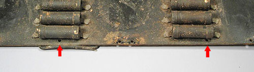
The front panel of the later unit has two additional holes that the earlier unit doesn't have, as shown in the above picture. Other pictures of CW-926A units that I have seen also have these holes. The explanation is found in the way the resistor subpanel is mounted. The two holes shown in the picture below never had screws in them (this side of the panel was closest to the front of the unit). If the resistors were installed on the panel first (the logical approach from a production standpoint), there is no way these screws could be installed. What they apparently did was to add additional brackets which strengthened the mounting system for this panel, hence the additional holes. |
|
 |
|
|
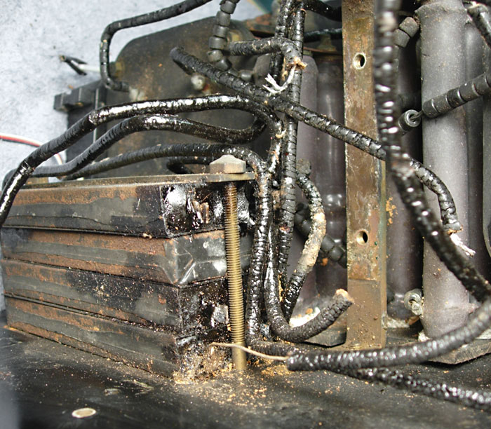
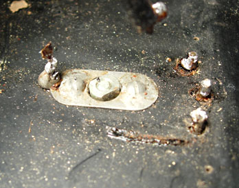
To make matters worse, one additional mounting screw
for this panel was missing. The lack of any marks or impressions
on the Bakelite panel where the head of the screw would have been
indicates that the screw had never been installed.
There was no clearance issue with this one. This was strictly a quality control problem. Only five of the eight screws were present, which might have led to breakage in severe conditions, especially considering that this panel was the sole support for the three transformers which collectively weigh about 15 lbs. There were other quality control problems as well. One of the volume control switch points was improperly installed, though it didn't affect the operation. Each of the small brass tags identifying the binding posts along the bottom of the panel is held in place by two brass escutcheon pins (tacks). Eight pilot holes were drilled for these pins. Then, for whatever reason, the workman decided they were in the wrong place, and he proceeded to drill another series of holes about 1/4 inch above the first set. The first set of holes were then filled in. Again, this was a cosmetic problem only. One of the phenolic pieces which hold the ends of the large resistors in position had not been made correctly, and was an interference fit once installed (the "U" shaped support bracket forced it out of the correct position so all of the resistors leaned a bit from perpendicular). I trimmed it to match the base piece, which is obviously what the designers intended. Finally, the workmanship exhibited by whoever wired this unit left much to be desired. It is generally not acceptable, particularly in military equipment, to lay the end of a wire against a lug and rely on the solder alone to make the connection secure and permanent. But that's exactly what was done in this unit in at least half of the connections. From a maintainability standpoint, the design was a nightmare. The difficulties caused by the punched or soldered hardware must have been considerable. Replacing any component, particularly a failed resistor would have required a major disassembly. So, this is an early unit, built as production was just starting up and, as always seems to be the case, in a rushed atmosphere of impending contract deadlines. Military electronics, in the 1917-18 period, was in its infancy. There was much yet to be learned. |
|